
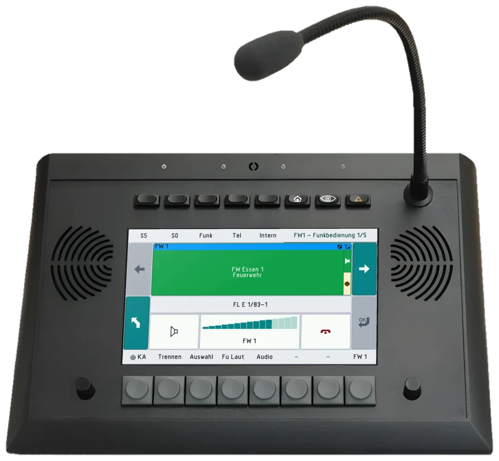
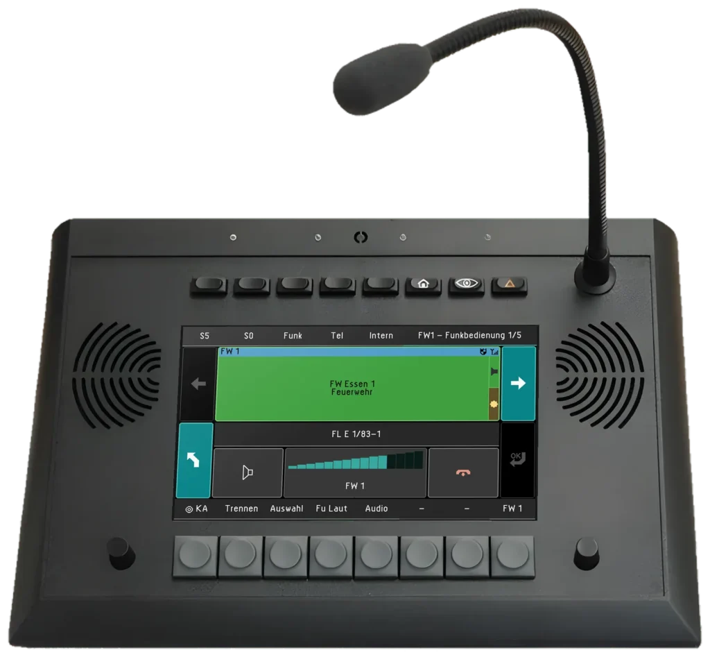
Desk units
UniKey-TS3
7″ touch desk unit for radio operation
In the tower, no single failure may interrupt radio. That is why every module is connected to two separate networks A and B, and two ZBE controllers work as a redundant pair: if a network, a switch or a controller fails, radio and telephony continue over the second path. Point at or click a component in the diagram to get to know it.
Three UniKey-TS3 positions in the tower, here for aerodrome control (TWR), ground control (GND) and clearance delivery (DEL), each with headset, footswitch and loudspeaker. Every UniKey has two network ports and is connected to network A and to network B.
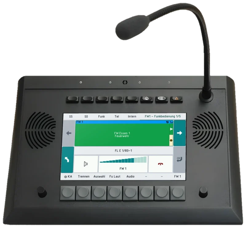 UniKey-TS3View product
UniKey-TS3 position of the apron control for the apron frequency, operational radio and telephony, also on network A and network B.
UniKey-TS3View product Second apron control position: AfVis with radio, telephony and video, audio via the ATL-IP module with handset, headset and footswitch; connected to network A and network B.
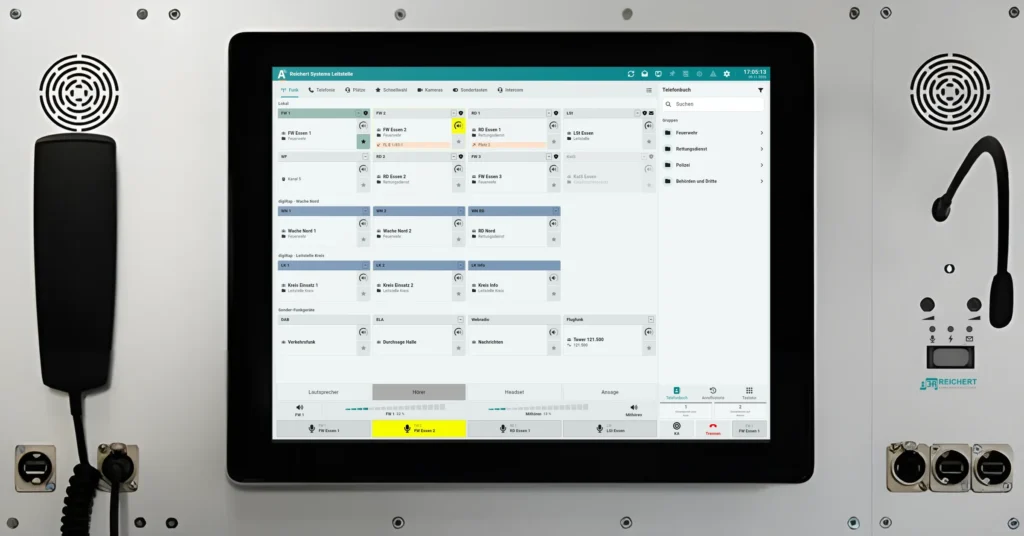 Software workstationView product
Two REICHERT ZBE controllers work as a fully redundant pair. Each controller is connected to network A and to network B; if one fails, the other takes over.
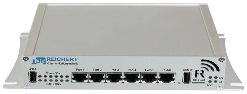 REICHERT ZBEView product
Two separate networks with their own switches and their own cables up into the tower and out to the ground radio stations. Every module is connected to both; if one network fails, operation continues over the other.
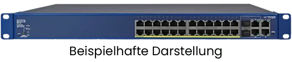 Network hardwareView product
Connection to the telephone system, for example for direct lines to neighbouring control units, the airport fire brigade and ground handling; connected twice like every module.
Connects local radios via radio connection cables, for example as standby radio or as operational radio to follow-me vehicles and ground handling; on networks A and B.
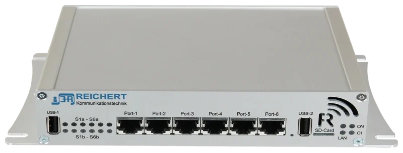 BOS-CompactView product
Transmitters and receivers of the air band frequencies to ED-137: main and standby station at separate sites, each with cables from network A and network B.
Supported radiosGo to radio connection
7″ touch desk unit for radio operation
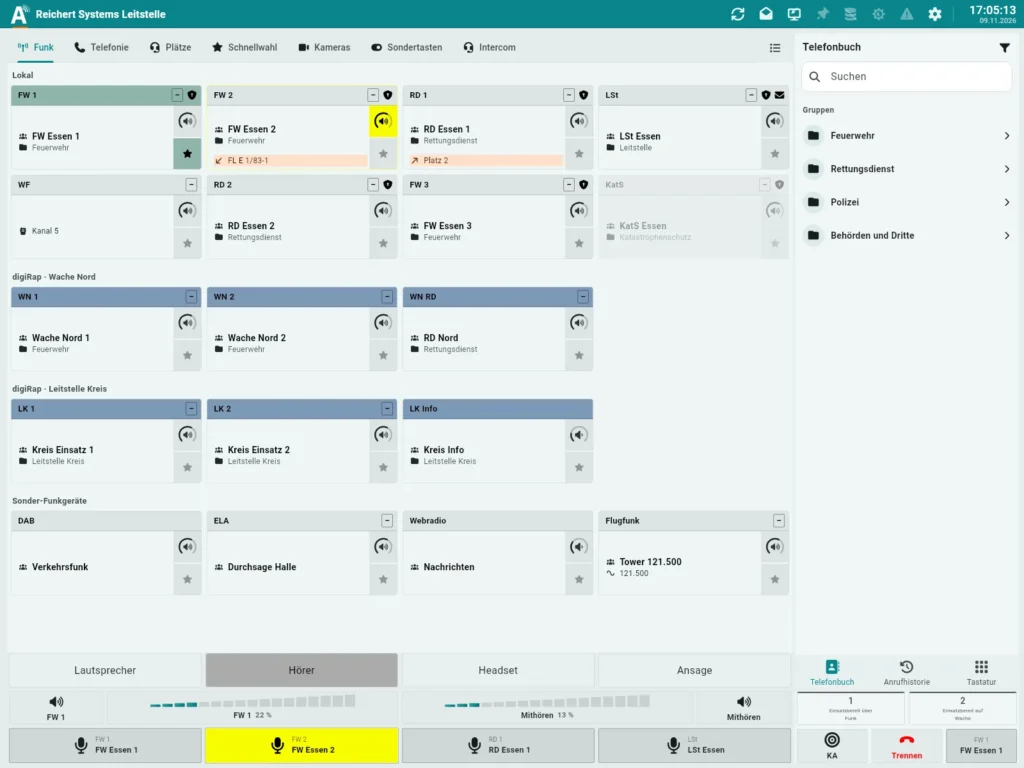
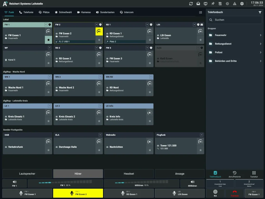
Software workstation = AfVis + ATL-IP module, on the network at the BOS-Compact
Central operating unit for radio, telephony, emergency
Switch and components for the system
Controller for radio, recording and telephony
As of 11/2026 · Example – every system is planned individually.
Tell us which vehicles or buildings you want to equip. We put together the matching configuration with you.